Last Updated on 31/08/2024 by Kevin Agar
Due to difficulties connecting nRF24 sensors to my heating system, because of distance problems, I decided to investigate using Bluetooth Low Energy (BLE) sensors, connected to a BLE to MQTT Gateway and communicating with MaxAir via a Mosquitto Broker. After researching what components I needed and the best way to go about it I finally decided for sensors I would use 4 Xiaomi Smart LCD Screen Digital Thermometer 2 Mijia Bluetooth Temperature Humidity Sensor model LYWSD03MMC which I purchased from AliExpress
For the WiFi BLE to MQTT Gateway I would use an ESP-WROOM-32 purchased from AliExpress
and for the Ethernet BLE to MQTT Gateway I would use a WT32-ETH01 purchased from AliExpress
Workflow
- Reprogram the LYWSD03MMC sensors with custom firmware
- Program the ESP-WROOM-32 with Tasmota32 Bluetooth (English)
- Program the WT32-ETH01 with Tasmota32 Bluetooth (English)
- Check all worked together and communicated with the Mosquitto Broker
1.
Reprogram the LYWSD03MMC sensors with custom firmware
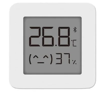
After an internet search, I came across a method of reprogramming these sensors wirelessly posted here
Although he did great initial work, he does state “Victor @pvvx did some very nice refinings of this custom firmware, so I really suggest checking it out, and even using his version as it offers many more functions including non-volatile storage and a better low power management”
So I followed the description that was posted here
It was easy to follow and I can’t think of any problems I had reprogramming them
2.
Program the ESP-WROOM-32 with Tasmota32 Bluetooth (English)
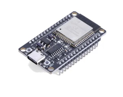
Note: You can’t program an ESP32 with Tasmotizer, you need to use the web installer at https://tasmota.github.io/install/
Connect the ESP-WROOM-32 via a USB cable to your PC and open the web installer page. Select Tasmota32 Bluetooth (English) by scrolling down the selection box.
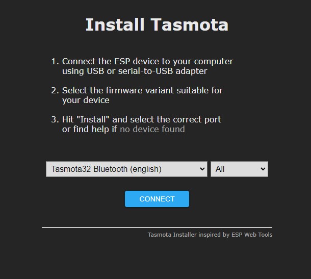
After selecting Tasmota32 Bluetooth (English) click the connect button which should open a popup.
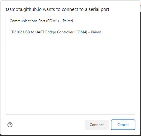
Select the port the ESP-WROOM-32 is connected to (which for me was COM4) and after a short time another popup appears
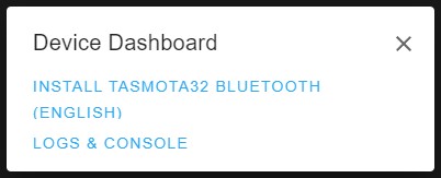
Click INSTALL TASMOTA32 BLUETOOTH (ENGLISH) and wait until the installation has completed
If it fails to work, try holding the EN button down when powering up the board
21/05/2024 Update
Bluetooth doesn’t appear to work with release version 14.0.0. So update as described and now the system will ask if you want to connect to WiFi. Select the correct SSID and add the password. You should then be redirected to the GUI of the tasmota device. (If this doesn’t work then use the method described below to add the WiFi credentials.) From here you can update the firmware by changing the OTA url to http://ota.tasmota.com/tasmota32/release-13.4.0/tasmota32-bluetooth.bin which is the last version that worked ok with bluetooth.
31/08/2024 Update
Bluetooth does work with release version 14.2.0.
Disconnect and then reconnect the ESP-WROOM-32 to USB power and it should be possible to connect to it with WiFi. To Connect you need to access the hotspot it creates with, for example, your phone, looking for a WiFi signal with a name something like tasmota-CA70C8-4296
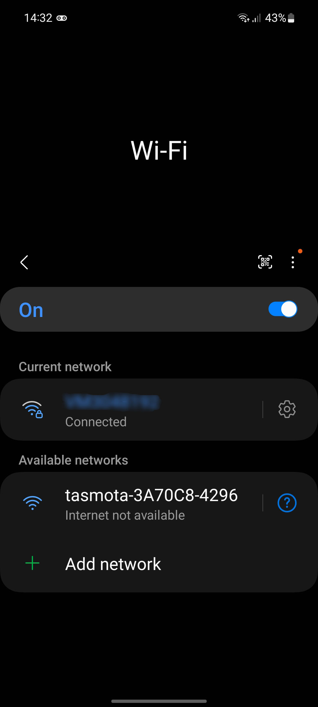
Once it’s connected, open a web browser and enter the address 192.168.4.1, then enter your WiFi credentials and Save.
You should now be able to access the BLE-MQTT Gateway on your network and set it up.
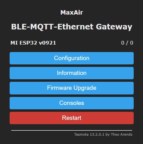
Click Configuration
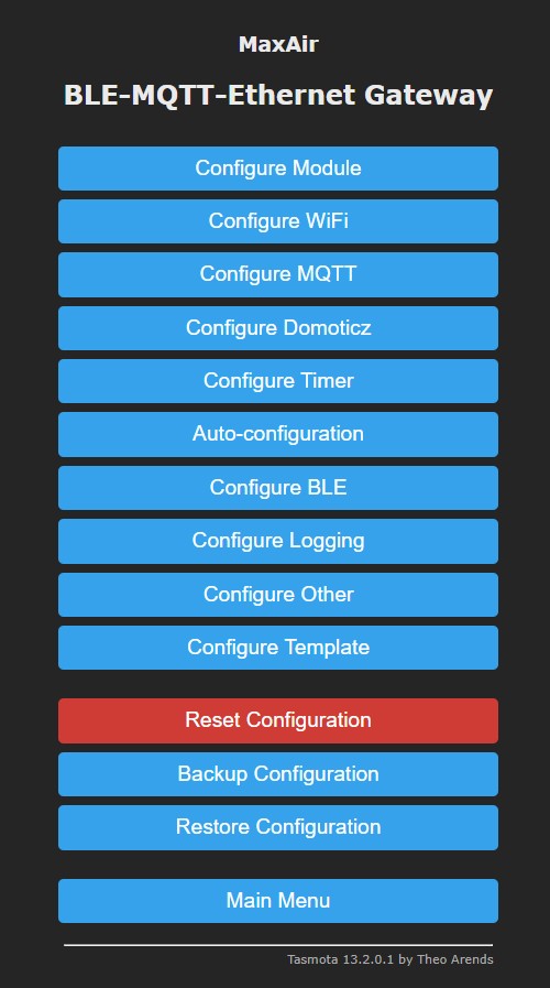
Click Configure BLE
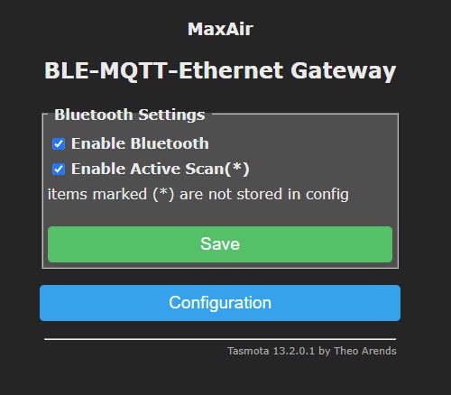
Select ‘Enable Bluetooth’ and ‘Enable Active Scan (*) then Save, Main Menu to return to the Home Screen
You should get
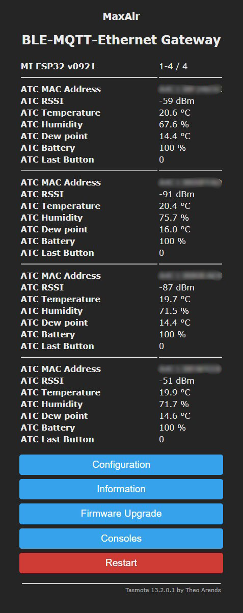
All sensor data is now being sent as MQTT messages but they are all together. To make things neater it would be better if each sensor sent it’s own MQTT message and had an Alias that meant something. To do this you need to add an autoexec.bat file.
Open your preferred text editor, (mine is Notepad++) create a new file, and enter (edit for your system. aaa.., bbb.., etc are the mac addresses of my LYWSD03MMC sensors )
MI32Topic BLED_Gateway
MI32Option6 1
BLEAlias aaaaaaaaaaaa=livingroom
BLEAlias bbbbbbbbbbbb=kevinroom
BLEAlias cccccccccccc=bedroom
BLEAlias dddddddddddd=backbedroom
WiFiPower 0
Save the file as autoexec.bat
If you want comments, then use the following, or add your own comments by starting the line with a semicolon ;
; Enter a name for the Gateway
MI32Topic BLED_Gateway
; The command to split the messages
MI32Option6 1
; Enter your Alias for your sensor with mac address aaaaaaaaaaaa
BLEAlias aaaaaaaaaaaa=livingroom
; Enter your Alias for your sensor with mac address bbbbbbbbbbbb
BLEAlias bbbbbbbbbbbb=kevinroom
; Enter your Alias for your sensor with mac address cccccccccccc
BLEAlias cccccccccccc=bedroom
; Enter your Alias for your sensor with mac address dddddddddddd
BLEAlias dddddddddddd=backbedroom
; Use this line if your WiFi is good as it reduces the power
WiFiPower 0
; The default is 1 which gives a value of 16, and 0 gives a value of 14
—————————
Now from the home screen, go to Consoles then Manage File system
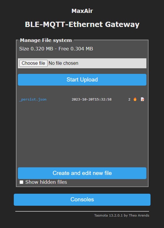
Click Choose file and select the file you’ve just created (autoexec.bat) then click Start Upload.
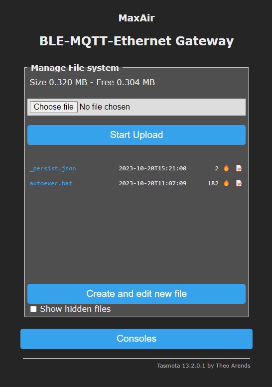
Reboot and you should now have
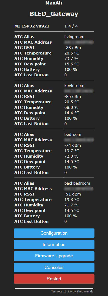
Open a console window and you will see the mqtt messages etc

I wanted all messages to be sent every minute, so in the enter command box I Typed TelePeriod 60 and hit enter
If you want a longer interval between measurements, then change the TelePeriod, eg. TelePeriod 120 for 2 minutes
To check what the TelePeriod value is then just type TelePeriod and it will return the actual value set.
3.
Program the WT32-ETH01 with Tasmota32 Bluetooth (English)
This is almost the same as programming the ESP-WROOM-32 except for the fact there isn’t a USB connector on the board and you have to connect a USB to serial board via jumper leads to the WT32-ETH01
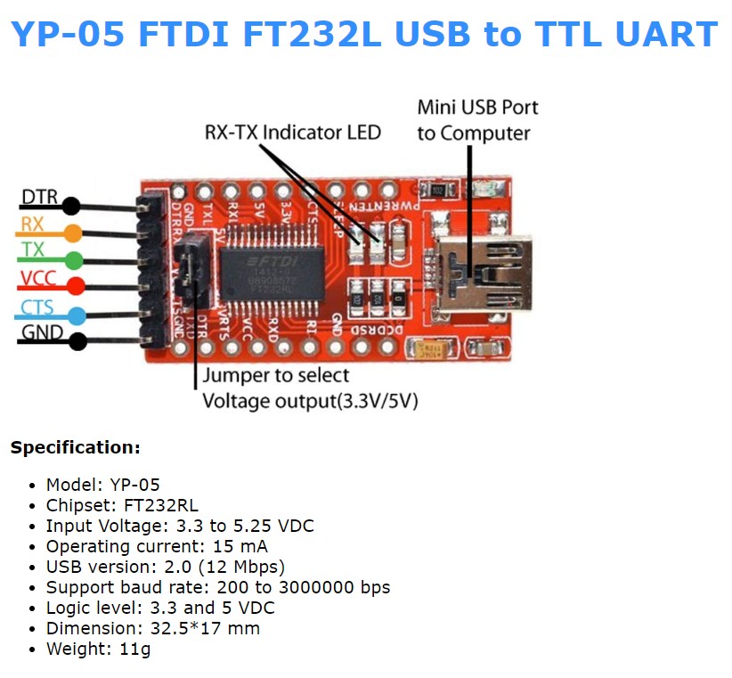
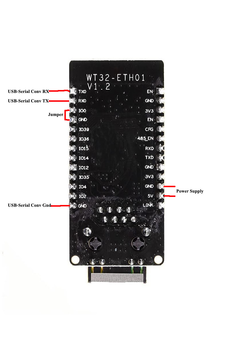
The settings for the WT32-ETH01 can be found here
Configuration for ESP32
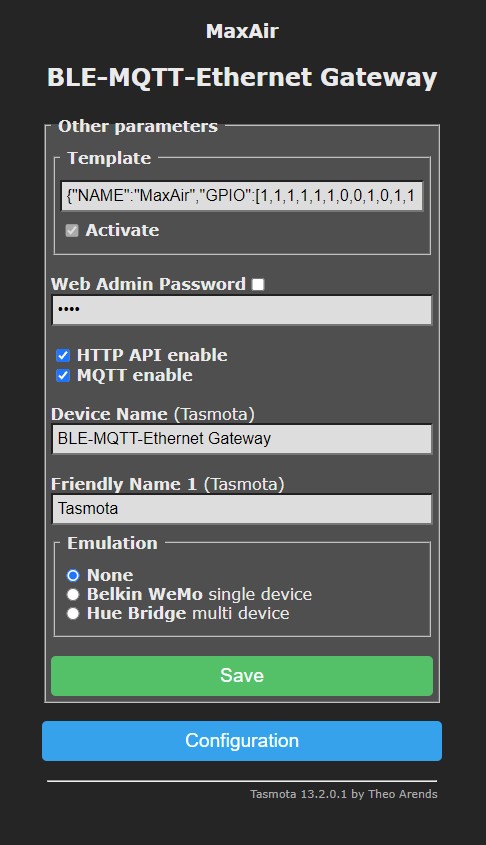
From the home screen go to Configuration and then Configure Other. Enter the following into the Template box, select Activate and then click Save
{“NAME”:”WT32_ETH01″,”GPIO”:[1,1,1,1,1,1,0,0,1,0,1,1,3840,576,5600,0,0,0,0,5568,0,0,0,0,0,0,0,0,1,1,0,1,1,0,0,1],”FLAG”:0,”BASE”:1}
You can change the name to whatever you want and my configuration is now
{“NAME”:”MaxAir”,”GPIO”:[1,1,1,1,1,1,0,0,1,0,1,1,3840,576,5600,0,0,0,0,5568,0,0,0,0,0,0,0,0,1,1,0,1,1,0,0,1],”FLAG”:0,”BASE”:1}
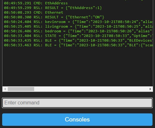
To configure for Ethernet you need to open the console window and enter
EthAddress 1
To check if it’s working type
EthAddress
it should return EthAddress 1
and
Ethernet
it should return Ethernet ON
4.
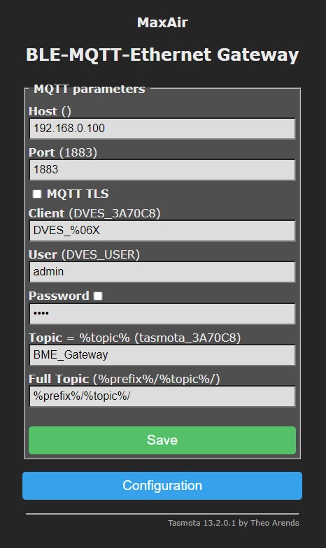
Finally you need to Configure the MQTT. From Home click Configuration then Configure MQTT. Enter your configuration and click Save
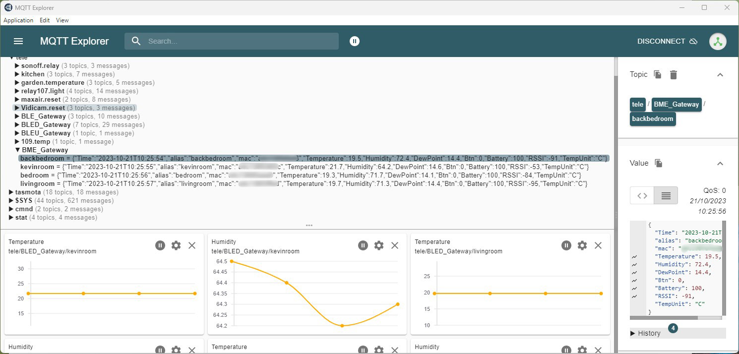
Check it’s all working by using MQTT Explorer
