Last Updated on 21/07/2022 by Kevin Agar
I’m getting a few communication errors with everything connected to the gateway. I think it’s time to change the gateway from WiFi to Ethernet
Parts ordered so far from Amazon
Arduino Pro Mini 328-3.3V/8MHz £12.72
Parts ordered from eBay
ENC28J60 Ethernet LAN Network Module Arduino Raspberry Pi £4.99
Radial Aluminium Electrolytic Capacitor 5 x 10uF 25V £1.65
50V Ceramic Disc Capacitor 10 x 100nF £1.45
AMS1117-3.3 surface mounted(SMD) voltage regulator x 5 £1.99
1:2 Splitter cable Micro USB socket to 2x Micro USB plug data syc £3.28
2 X Set 2.54mm Breakaway PCB 40 Pin Male Female Header Connector For Arduino £1.75
Total £27.83
At the moment things have ground to a halt. My WiFi gateway main board is an old style board, so can’t really be upgraded, so I’m waiting for a new board from Pihome.eu. On top of this, the ethernet board, W5100, is hard to come by. I’ve ordered one from Aliexpress but don’t expect to get it this month. So far, I’ve got the Arduino Pro Mini 328-3.3V/8MHz but am waiting for the main board, and ethernet board. When these arrive I’ll be able to carry on. I’ve decided not to use the ENC28J60 Ethernet LAN Network Module Arduino Raspberry Pi as it requires a different mother board
To check everything is ok I decided to program the arduino using Arduino IDE
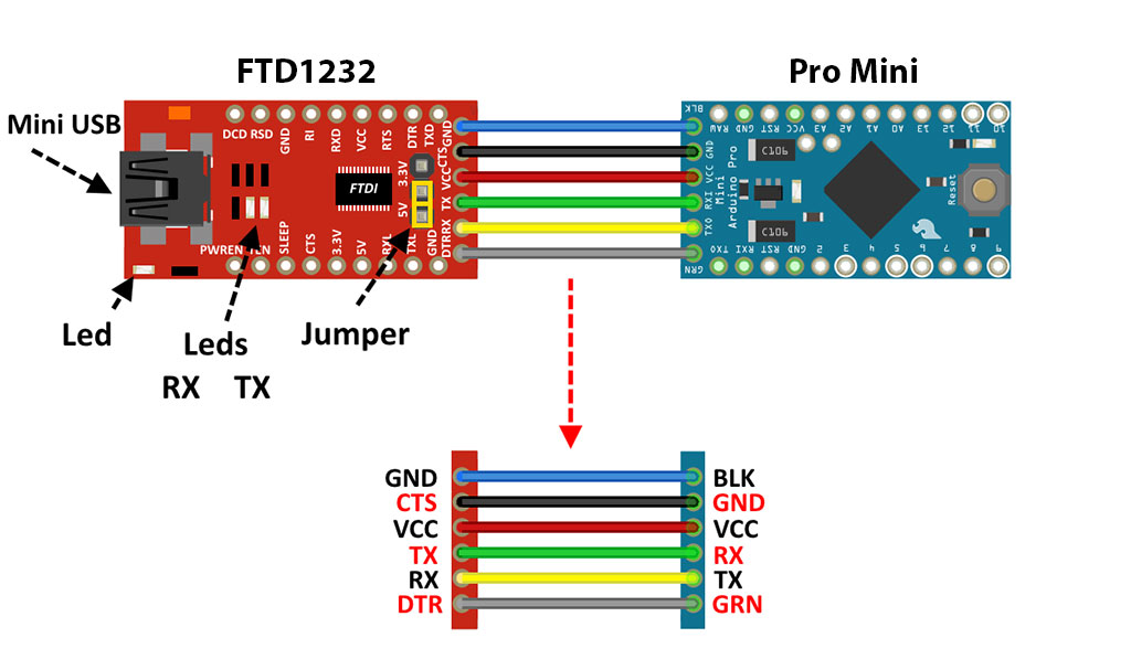
Connect the boards as in the image below

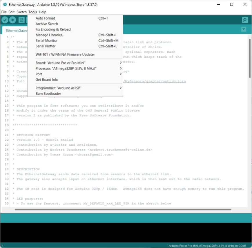
Set the Arduino IDE to the following settings on port COM5 (this could change)

Download the latest sketch to the Arduino IDE and upload it to the Arduino Pro Mini 328-3.3V/8MHz board
/*
 * The MySensors Arduino library handles the wireless radio link and protocol
 * between your home built sensors/actuators and HA controller of choice.
 * The sensors forms a self healing radio network with optional repeaters. Each
 * repeater and gateway builds a routing tables in EEPROM which keeps track of the
 * network topology allowing messages to be routed to nodes.
 *
 * Created by Henrik Ekblad <henrik.ekblad@mysensors.org>
 * Copyright (C) 2013-2018 Sensnology AB
 * Full contributor list: https://github.com/mysensors/MySensors/graphs/contributors
 *
 * Documentation: http://www.mysensors.org
 * Support Forum: http://forum.mysensors.org
 *
 * This program is free software; you can redistribute it and/or
 * modify it under the terms of the GNU General Public License
 * version 2 as published by the Free Software Foundation.
 *
 *******************************
 *
 * REVISION HISTORY
 * Version 1.0 - Henrik EKblad
 * Contribution by a-lurker and Anticimex,
 * Contribution by Norbert Truchsess <norbert.truchsess@t-online.de>
 * Contribution by Tomas Hozza <thozza@gmail.com>
 *
 *
 * DESCRIPTION
 * The EthernetGateway sends data received from sensors to the ethernet link.
 * The gateway also accepts input on ethernet interface, which is then sent out to the radio network.
 *
 * The GW code is designed for Arduino 328p / 16MHz.  ATmega168 does not have enough memory to run this program.
 *
 * LED purposes:
 * - To use the feature, uncomment MY_DEFAULT_xxx_LED_PIN in the sketch below
 * - RX (green) - blink fast on radio message received. In inclusion mode will blink fast only on presentation received
 * - TX (yellow) - blink fast on radio message transmitted. In inclusion mode will blink slowly
 * - ERR (red) - fast blink on error during transmission error or receive crc error
 *
 * See http://www.mysensors.org/build/ethernet_gateway for wiring instructions.
 *
 */

// Enable debug prints to serial monitor
#define MY_DEBUG

// Enable and select radio type attached
#define MY_RADIO_RF24
//#define MY_RADIO_NRF5_ESB
//#define MY_RADIO_RFM69
//#define MY_RADIO_RFM95

//NRF Radio Related Custom Configuration.
#define MY_RF24_PA_LEVEL RF24_PA_MAX
//#define MY_DEBUG_VERBOSE_RF24

// RF channel for the sensor net, 0-127
#define MY_RF24_CHANNEL  91
//RF24_250KBPS for 250kbs, RF24_1MBPS for 1Mbps, or RF24_2MBPS for 2Mbps
#define RF24_DATARATE      RF24_250KBPS

// Enable gateway ethernet module type
#define MY_GATEWAY_W5100

// W5100 Ethernet module SPI enable (optional if using a shield/module that manages SPI_EN signal)
//#define MY_W5100_SPI_EN 4

// Enable Soft SPI for NRF radio (note different radio wiring is required)
// The W5100 ethernet module seems to have a hard time co-operate with
// radio on the same spi bus.
#if !defined(MY_W5100_SPI_EN) && !defined(ARDUINO_ARCH_SAMD)
#define MY_SOFTSPI
#define MY_SOFT_SPI_SCK_PIN 14
#define MY_SOFT_SPI_MISO_PIN 16
#define MY_SOFT_SPI_MOSI_PIN 15
#endif

// When W5100 is connected we have to move CE/CSN pins for NRF radio
#ifndef MY_RF24_CE_PIN
#define MY_RF24_CE_PIN 5
#endif
#ifndef MY_RF24_CS_PIN
#define MY_RF24_CS_PIN 6
#endif

// Enable UDP communication
//#define MY_USE_UDP  // If using UDP you need to set MY_CONTROLLER_IP_ADDRESS below

// Enable MY_IP_ADDRESS here if you want a static ip address (no DHCP)
//#define MY_IP_ADDRESS 10,0,0,100

// If using static ip you can define Gateway and Subnet address as well
//#define MY_IP_GATEWAY_ADDRESS 10,0,0,1
//#define MY_IP_SUBNET_ADDRESS 255,255,255,0

// Renewal period if using DHCP
//#define MY_IP_RENEWAL_INTERVAL 60000

// The port to keep open on node server mode / or port to contact in client mode
#define MY_PORT 5003

// Controller ip address. Enables client mode (default is "server" mode).
// Also enable this if MY_USE_UDP is used and you want sensor data sent somewhere.
//#define MY_CONTROLLER_IP_ADDRESS 192, 168, 178, 254

// The MAC address can be anything you want but should be unique on your network.
// Newer boards have a MAC address printed on the underside of the PCB, which you can (optionally) use.
// Note that most of the Arduino examples use  "DEAD BEEF FEED" for the MAC address.
//#define MY_MAC_ADDRESS 0xDE, 0xAD, 0xBE, 0xEF, 0xFE, 0xED

// Enable inclusion mode
#define MY_INCLUSION_MODE_FEATURE
// Enable Inclusion mode button on gateway
//#define MY_INCLUSION_BUTTON_FEATURE
// Set inclusion mode duration (in seconds)
#define MY_INCLUSION_MODE_DURATION 60
// Digital pin used for inclusion mode button
//#define MY_INCLUSION_MODE_BUTTON_PIN  3

// Set blinking period
#define MY_DEFAULT_LED_BLINK_PERIOD 300

// Flash leds on rx/tx/err
// Uncomment to override default HW configurations
#define MY_DEFAULT_ERR_LED_PIN 8  // Error led pin
#define MY_DEFAULT_RX_LED_PIN  7  // Receive led pin
#define MY_DEFAULT_TX_LED_PIN  4  // Transmit led pin
#define MY_WITH_LEDS_BLINKING_INVERSE

#if defined(MY_USE_UDP)
#include <EthernetUdp.h>
#endif
#include <Ethernet.h>
#include <MySensors.h>

void setup()
{
	// Setup locally attached sensors
}

void presentation()
{
	// Present locally attached sensors here
}

void loop()
{
	// Send locally attached sensors data here
}
Well, time and technology move on. Whilst looking at changing the gateway, there is a new board, WT32-ETH01, that does everything needed but in a compact unit. Terry has created a pcb for the WT32 and written a sketch for it as well. This board is far superior to the previous ethernet board above, so I have stopped this project and converted to the WT32 instead. This journey can be found in MaxAir – Gateway using a WT32-ETH01.