Last Updated on 10/09/2023 by Kevin Agar
Following on from my post Changing MaxAir gateway from WiFi to Ethernet, this is the latest iteration of the Gateway that can be set as either WiFi or Ethernet in a compact package.
The gateway is using a WT32-ETH01 that can be purchased at numerous outlets, for example, AliExpress, eBay, Amazon, etc
It also uses an NRF24L01+PA+LNA module that can be purchased at numerous outlets, for example, AliExpress, eBay, Amazon, etc
Terry, the main developer of this gateway for MaxAir, has created a board to mount everything on. I’m not sure if he has this board for sale but he can be contacted at Discord>PiHome HVAC
The sketch can be downloaded from MaxAir at https://github.com/twa127/PiHomeHVAC/tree/main/Arduino_Sketches/nRF24L01/MaxAir_GatewayWT32_ETH01_v002
or from the MaxAir controller at /var/www/Arduino_Sketches/nRF24L01/MaxAir_GatewayWT32_ETH01_v002
The README.md file below gives information about the gateway and what’s needed to program it.
Version 2 PCB Gateway sketch for WT32-ETH01 wireless-tag board.
Implements WirelessManager.
Can be configured for NRF24L01, or RFM69 or RFM95 wireless modules.
Jumper for WiFi only mode.
Jumper for Ethernet only mode.
Jumper to clear EEPROM of saved wireless credentials.
Connection can be either WiFi or Ethernet or both.
Jumper for Relay Module trigger LOW (no jumper) or HIGH (jumper).
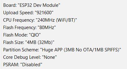
Compiled as ESP32 Dev Module.
Can be used with Version 1 PCBs and Version 2 PCBs without the PCF8575 i2c I/O Expander by setting environment variables within the sketch.
Pin Usage
| Pin Name | Function |
|---|---|
| TX0 | Serial OUT |
| RX0 (IO3) | Serial IN and i2c SCL |
| IO0 | Program Select Jumper (10K Pullup Resistor to 3V3) |
| IO2 | Radio MOSI |
| IO4 | Radio CE |
| TXD (IO5) | Set Relay Trigger HIGH or LOW (10K Pullup Resistor to 3V3) |
| IO12 | Radio MISO |
| IO14 | Radio SCK |
| IO15 | Radio SS |
| RXD (IO17) | RX LED |
| CFG (IO32) | Clear WiFi Credentials Jumper (10K Pullup Resistor to 3V3) and i2c SDA |
| 485_EN (IO33) | TX LED |
| IO35 | ERR LED |
| IO36 | Radio IRQ (10K Pullup Resistor to 3V3) |
| IO39 | Used as ADC, Disable WiFi (low), Disable Ethernet (High) |
| 5V | 5volt Power Input |
| 3V3 | 3.3volt Power Out to Radio |
| GND | Common Ground |
Install support for ESP32 boards by using File>Preferences>Addional Boards Manager URL: https://dl.espressif.com/dl/package_esp32_index.json and searching for esp32
Board type to be selected is ‘ESP32 Dev Module’
The sketch uses WiFiManager and WebServer_WT32_ETH01 libraries and requires a change to the file MyGatewayTransportEthernet.cpp.
In the Arduino IDE install the ZIP library WebServer_WT32_ETH01.zip
Copy the folder WiFiManager to …\Documents\Arduino\libraries
Modify the file …\Documents\Arduino\libraries\MySensors\core\MyGatewayTransportEthernet.cpp as per the instructions at https://www.pihome.eu/2021/10/06/wifimanager-with-mysensors/
Here are the main points
Edit the file Documents\Arduino\libraries\MySensors\core\MyGatewayTransportEthernet.cpp
Comment out line 49 to 55
| 49 50 51 52 53 54 55 | /* #if defined(MY_GATEWAY_ESP8266) || defined(MY_GATEWAY_ESP32) #if !defined(MY_WIFI_SSID) #error ESP8266/ESP32 gateway: MY_WIFI_SSID not defined! #endif #endif */ |
Also comment out lines 184 to 189
| 184 185 186 187 188 189 | /* (void)WiFi.begin(MY_WIFI_SSID, MY_WIFI_PASSWORD, 0, MY_WIFI_BSSID); while (WiFi.status() != WL_CONNECTED) { delay(1000); GATEWAY_DEBUG(PSTR(“GWT:TIN:CONNECTING…\n”)); } GATEWAY_DEBUG(PSTR(“GWT:TIN:IP: %s\n”), WiFi.localIP().toString().c_str());*/ |
In the Arduino IDE install the Library PCF8575 by Renzo Mischianti
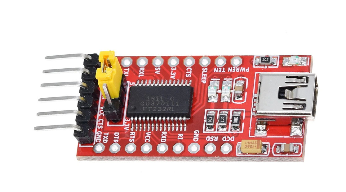
To upload the sketch to the WT32-ETH01 use a USB To TTL FT232RL FTDI Serial Adapter Converter Module or similar

on the USB->TTL Flasher:
Set the “Jumper” to S1 and 5V and not S1 and 3.3V
Programming mode:
